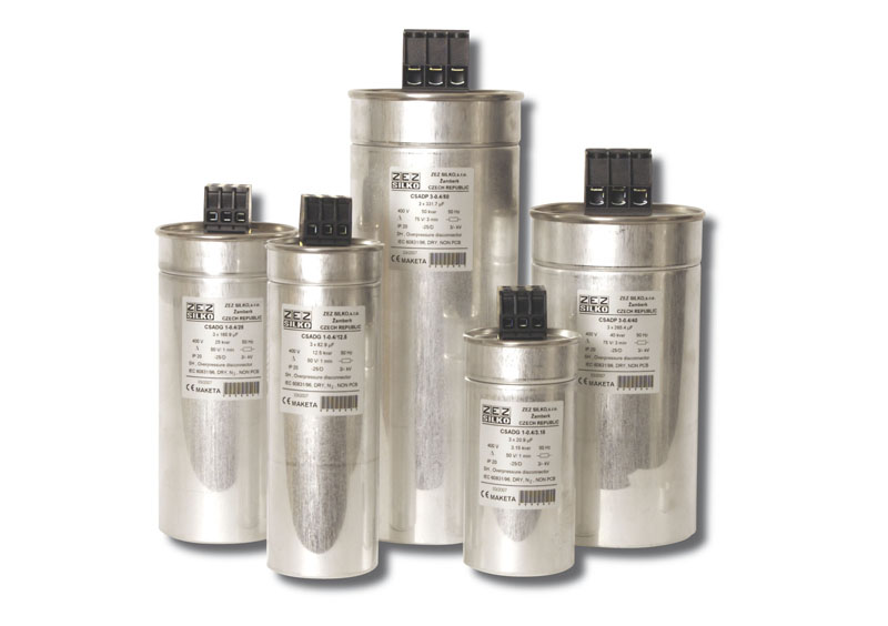
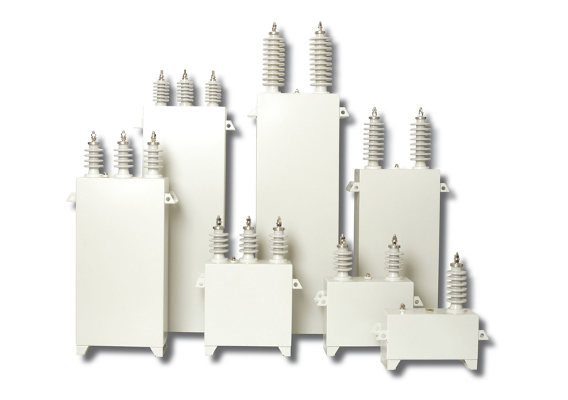
 Power capacitors


Technical data
Under normal operating conditions some electrical equipment (electric motors, welding machines, fluorescent lamps) consumes not only active energy from the power line, but also reactive energy. From the physical viewpoint, the reactive energy is necessary to secure a correct function of these devices. However, sum of both energies applies load to transmission networks. The effort is to connect correctly designed capacitor to the appliance, which supplies the reactive energy directly to the appliance. This reduces the amount of reactive energy transmitted through the power line. This solution is designated as the power factor correction.
The quality of PF correction is given by the power factor cos j, which is a ratio of real and apparent power. The ideal goal is to achieve cos j = 1. Usually customer is penalized for the power factor lower than 0.95.
The following types of PF correction are used: individual, group and central. In case of individual PF correction the capacitor is switched directly with the appliance. Group and central PF correction are suitable for more extensive electrical systems with variable loading. Switching of capacitors is controlled by the microprocessor controller, which ensures achievement of the optimum power factor.
The reactive power necessary to achieve the power factor required:
QC = P x [tg(arcos(cos j1)) – tg(arcos(cos j2))]
QC - reactive power of the capacitor required
P - real power of the appliance
cos j1 - original power factor
cos j2 - resulting power factor
Development of semiconductor technology has adverse impacts on the alternating current network. Sinusoidal waveform gets distorted by consumption of the reactive energy with non-sinusoidal pattern of currents. Distortion can be expressed by the content of higher harmonics. The content of harmonics results in increase of capacitor current, since its impedance decreases with increasing frequency. This may cause damage to capacitor, unsatisfactory tripping of circuit breakers and incorrect operation of the end equipment. This situation can be resolved by installation of capacitors with reactors (detuned PF correction), which attenuate the resonance circuit and such installation has also a partial filtering effect – it reduces the distortion level in the network. It is recommended in situations, where the share of equipment generating higher harmonics exceeds 20% of the total load. Filtering circuits are used for removal of higher percent share of harmonics from the network.
Capacitor in detuned PF correction is exposed to higher than network voltage. This is caused by serial connection of the reactor and capacitor.
Capacitors are produced in MKP and MKV systems. Both dielectric systems are self-healing. Metal plated layer is evaporated in case of the voltage breakdown. Formed insulating surface is very small and does not effected the functionality of the capacitor. Capacitors windings are inserted into
aluminum container. Container is equipped with the overpressure disconnector.
MKP capacitors are made of one-side metallized PP film. Contacting of the winding is performed by zinc spraying. This configuration is dry without impregnant.
As for MKV capacitor, electrodes are of metallized paper on both sides and PP foil serves as a dielectric. The system is impregnated by mineral oil. MKV capacitors are thus suitable for higher power loading and higher ambient temperature.
Fuses and cross-section of conductors
PF correction capacitors should be provided with fuses with a slow breaking characteristic (gG). Cross-section of conductors should be sized to at least 1.5 multiple of capacitor’s rated current (see table – recommended cross-sections of conductors and sizing of fuses).
Connection of capacitors shall be performed only by Cu conductors based on the following table.
Rated current
of three-phase
capacitor
[A] |
Three-phase
compensating
power at 400 V
[kvar] |
Recommended cross-section
of connection bundled
Cu conductors
[mm2] |
Fuse
rated
current
[A] |
|
2,9 |
2 |
2,5 |
8 |
|
3,6 |
2,5 |
2,5 |
8 |
|
4,5 |
3,15 |
2,5 |
10 |
|
5,8 |
4 |
2,5 |
10 |
|
7,2 |
5 |
2,5 |
16 |
|
9 |
6,25 |
2,5 |
16 |
|
11,5 |
8 |
4 |
20 |
|
14,4 |
10 |
4 |
25 |
|
18,1 |
12,5 |
6 |
32 |
|
21,7 |
15 |
6 |
40 |
|
28,8 |
20 |
10 |
50 |
|
36,1 |
25 |
10 |
63 |
|
43,4 |
30 |
16 |
80 |
|
50,5 |
35 |
16 |
100 |
|
57,7 |
40 |
25 |
100 |
|
72,2 |
50 |
25 |
125 |
|
86,6 |
60 |
35 |
160 |
|
115,5 |
80 |
70 |
200 |
|
144,3 |
100 |
95 |
250 |